Most operators making AI infrastructure decisions in 2026 are getting them wrong — but not for the reason the trade press is telling them.
The mistake isn’t picking the wrong voltage class, or backing the wrong supplier, or being too late to commit. The mistake is treating the architecture as monolithic. As if “we’re going 800 V” or “we’re committing to Mt. Diablo” were a single decision rather than what it actually is: a stack of six decisions, one per layer, each with its own vendors, standards, timelines, and commercial logic.
The smart operators aren’t choosing between 800 V and ±400 V. They’re choosing per layer. Their Layer 2 decision (perimeter conversion) doesn’t dictate their Layer 4 decision (rack-level conversion); their Layer 3 decision (building distribution) is separable from their Layer 5 decision (in-rack busbar). They make commitments where commitments earn them something, and preserve optionality everywhere else.
The operators getting it wrong are the ones treating the headline voltage choice as if it determined everything below it. It doesn’t. And the cost of that mistake — measured in stranded capex, vendor lock-in, and capacity that can’t accept the next generation of accelerator — compounds over the 15-25 year operational life of the facility.
This essay is the framework. The essays that follow in this series — on solid-state transformers, sidecar power racks, BESS coupling, connectors, the value chain — each go deep on one of these layers. Before we get there, you need the map.
A note before we start
This essay is structural rather than argumentative. The point isn’t to convince you that one architecture wins. The point is to make sure that when you’re reading any of the next ten essays, you know which layer of the stack the argument is happening at, and what the layer above and below are doing.
If §1 of this essay reads like reference material — that’s intentional. Treat it as such. Bookmark it. Come back to it.
1. The six layers
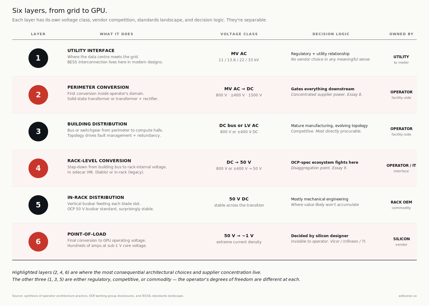
From the utility connection to the GPU pin, every AI data centre passes power through six distinct layers. The voltage transitions, the conversion stages, and the protection regimes are different at each.
Layer 1 — Utility interface. Where the data centre meets the grid. Medium-voltage AC delivery (typically 13.8 kV in North America, 11 or 22 kV in Europe and most of Asia, 33 kV in some industrial-park contexts). Owned by the utility up to the meter; owned by the operator from the meter inward. This is also where the BESS interconnection lives in modern designs.
Layer 2 — Perimeter conversion. The first equipment inside the operator’s domain. Historically a step-down transformer to low-voltage AC; in DC architectures, this is increasingly a solid-state transformer (SST) producing DC directly at 800 V, ±400 V, or in some emerging designs at 1500 V. The design choice here gates everything downstream.
Layer 3 — Building distribution. The DC bus or AC distribution that carries power from the perimeter conversion to the compute halls. In NVIDIA’s row-scale architecture, this is the bus that runs along each row. In Mt. Diablo’s architecture, this is the medium-voltage feed to each sidecar power rack. In legacy AC, this is the LV switchgear and busway. Topology matters enormously here for fault management and redundancy.
Layer 4 — Rack-level conversion. The step from building-distribution voltage to the voltage the rack can use internally. In NVIDIA reference, the conversion happens in a sidecar power rack adjacent to (but feeding) compute racks. In Mt. Diablo, the conversion happens in a sidecar serving the IT rack as well. In legacy 48 V architectures, this conversion happened in the IT rack itself via the power shelf. The disaggregation of this layer from the IT rack is one of the bigger structural shifts in the transition.
Layer 5 — In-rack distribution. The busbar that runs vertically through the IT rack, distributing power to each blade slot. This is the layer where the 50 V class still dominates regardless of what’s happening above. The 50 V busbar standard is OCP’s contribution from a decade ago and it’s stayed surprisingly stable through the transition.
Layer 6 — Point-of-load. The final conversion from 50 V to the GPU’s actual operating voltage (a small handful of volts at very high current — Vera Rubin is hundreds of amps at sub-1 V core voltage). This is where Vicor, Infineon, Texas Instruments, and a handful of other suppliers fight a quiet but consequential battle. The decisions made here affect efficiency, cooling, and silicon longevity.
The layers aren’t independent. A choice at Layer 2 (SST topology) constrains what’s possible at Layer 3 (which busbar architectures work) which constrains Layer 4 (which sidecar designs are viable). But the layers are separable in a way that the marketing doesn’t always make clear. An operator can run NVIDIA-reference Layer 4 and Mt. Diablo-style Layer 3 if they’re willing to engineer the interface. Most won’t, but the option exists.
2. The standards landscape (and why it’s fragmented)
If you ask three different industry working groups what governs DC architecture in data centres, you’ll get three different answers, partly because each group’s scope covers different layers. The standards landscape is fragmented along organizational lines that have nothing to do with the operator’s view of the system.
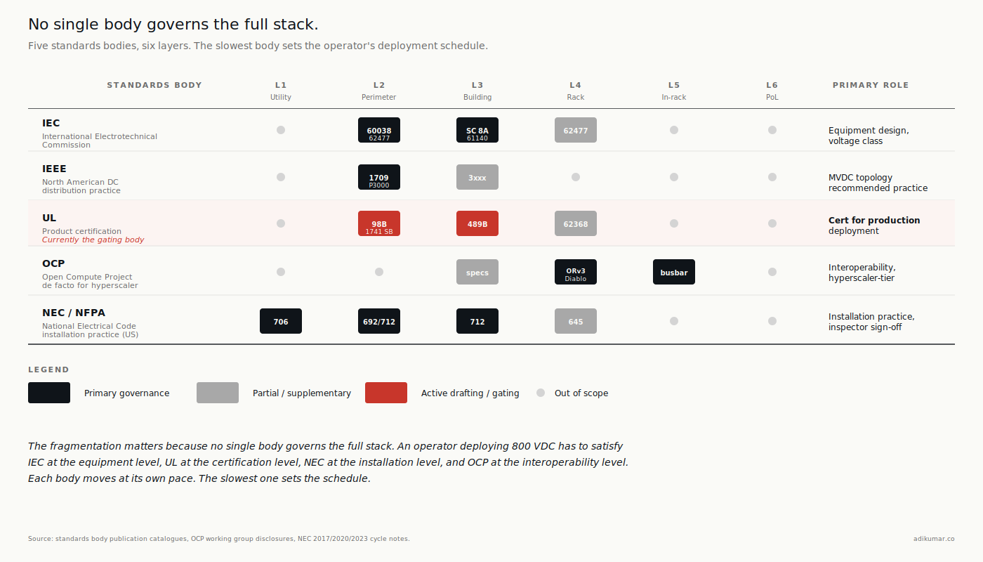
Five bodies matter for the next five years.
IEC (International Electrotechnical Commission). Authoritative globally for voltage classification and equipment design. IEC 60038 defines the voltage classes (LVDC, MVDC, HVDC) — this is the standard Essay 1 leaned on for the terminology correction. IEC 61140 covers protection against electric shock and is being supplemented for DC applications. IEC 62477 covers safety for power electronic converters. IEC SC 8A is a relatively new subcommittee specifically for LVDC distribution systems, where most of the active drafting work is happening.
IEEE. Authoritative in North America for DC distribution practice. IEEE 1709 is the recommended-practice standard for medium-voltage DC distribution on shipboard and industrial applications, and the next revision is being watched as a possible reference for stationary data centres at higher voltage classes. IEEE P3000 and the 3xxx series cover broader power systems engineering.
UL. Authoritative for product certification in North America. UL 98B (DC disconnect switches up to 1500 V) is the standard most often cited, and the standard most often misunderstood — as Essay 2 noted, ABB’s 2 kV cert was a stretch case ahead of UL writing the broader voltage range into the standard. UL 489B for DC molded-case circuit breakers. UL 1741 SB for grid-interactive equipment. UL 924 for emergency lighting (relevant for facility-level coordination). UL is currently the gating body for whether 800 V data centre topologies move from “engineerable” to “certifiable for production deployment.”
OCP (Open Compute Project). Not a standards body in the formal sense — OCP publishes specifications that members agree to interoperate against. But OCP specs (ORv3, ORv3 HPR, Mt. Diablo) function as de facto standards for hyperscaler-tier deployment because the spec authors are also the largest deployers. The Diablo 400 specification (v0.7.0, March 2026) is the most consequential current work.
NEC / NFPA (National Electrical Code). Authoritative for installation practice in the US. NEC Article 692 (PV systems, DC-relevant), Article 706 (energy storage systems), Article 712 (DC microgrids — added in the 2017 cycle, refined since). The NEC is where the standards from above intersect with what an electrical inspector will sign off on. The gap between “the standard exists” and “the inspector is comfortable with it” can be years.
The fragmentation matters because no single body governs the full stack. An operator deploying 800 VDC has to satisfy IEC at the equipment-design level, UL at the product-certification level, NEC at the installation level, and OCP at the interoperability level. Each body moves at its own pace. The slowest one sets the schedule.
This is also why the standards-extension story (UL 98B coverage above 1500 V, IEC SC 8A new working drafts, IEEE 1709 next revision) is the most-watched thread in the industry. It’s not that the technology isn’t ready. It’s that four different bodies need to agree on what “ready” means before the inspector signs the certificate.
3. The vendor map by layer
The vendor landscape isn’t homogeneous across the stack. At each layer, the competitive structure is different.
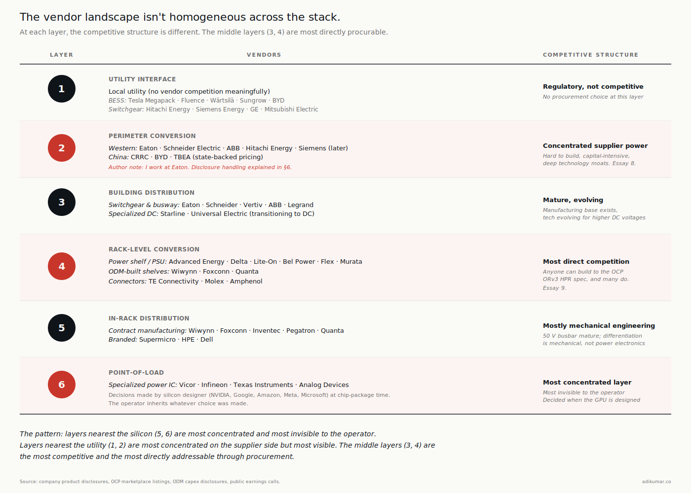
Layer 1 (Utility interface). Operator’s own engineering team plus the utility. No vendor competition at this layer in any meaningful sense — the vendor is the local utility, and the relationship is regulatory more than commercial. Where there’s vendor activity, it’s around interconnection equipment and BESS aggregation: Tesla Megapack, Fluence, Wärtsilä, Sungrow, BYD on the BESS side; the same pool of utility-class transformer and switchgear OEMs (Hitachi Energy, Siemens Energy, GE, Mitsubishi Electric) on the interconnection side.
Layer 2 (Perimeter conversion / SST). This is where the most concentrated supplier power emerges as the transition deepens. SSTs are hard to build, capital-intensive, and protected by deep technology moats. The credible Western vendor list is short: Eaton, Schneider Electric, ABB, Hitachi Energy. Siemens is in the conversation but later. On the Chinese side, CRRC, BYD, and TBEA are credible at scale and benefit from state-backed pricing. Essay 8 will dive deeper here.
(Author note for transparency: I work at Eaton. I’ll say more in §6 about how I’m handling that disclosure across this series.)
Layer 3 (Building distribution). Busway and switchgear vendors. Eaton, Schneider, Vertiv, ABB, Legrand. Plus specialized DC busway suppliers (Starline, Universal Electric on the AC side moving toward DC). The vendor structure here is mature; the technology has to evolve to handle DC distribution at higher voltages but the manufacturing base exists.
Layer 4 (Rack-level conversion). Power shelf and PSU vendors. Advanced Energy, Delta Electronics, Lite-On, Bel Power Solutions, Flex Power Modules, Murata, plus the ODM-built shelves from Wiwynn, Foxconn, Quanta. Also the connector vendors who define the interface (TE Connectivity, Molex, Amphenol). This is the layer where the OCP spec ecosystem creates the most direct vendor competition — anyone can build to the ORv3 HPR spec, and many do.
Layer 5 (In-rack distribution). Busbar manufacturers and rack OEMs. Mostly the rack OEMs themselves (Wiwynn, Foxconn, Inventec, Pegatron, Quanta on the contract manufacturing side; Supermicro, HPE, Dell on the branded side). The 50 V busbar is mature technology and the differentiation is mostly mechanical engineering, not power electronics.
Layer 6 (Point-of-load). A small handful of specialized power IC suppliers. Vicor, Infineon, Texas Instruments, Analog Devices (post-Maxim). This is the most concentrated layer and the one most invisible to the operator buying conversation. Decisions here are made by the silicon designer (NVIDIA, Google, Amazon, Meta, Microsoft) when they design their accelerator package, and the operator inherits whatever choice was made.
The pattern is worth noticing: the layers nearest the silicon (5 and 6) are the most concentrated and the most invisible to the operator. The layers nearest the utility (1, 2) are the most concentrated on the supplier side but most visible. The middle layers (3, 4) are the most competitive and the most directly addressable through procurement.
When the rest of this series talks about “where the value goes” in the DC transition, layers 2, 3, and 4 are where most of it will go. Layer 6 is where it already is. Layer 5 is where it likely won’t be.
4. The hybrid reference architecture (sketched)
Here’s the unpopular fact: most operators won’t deploy a pure NVIDIA 800 VDC architecture or a pure Mt. Diablo architecture. They’ll deploy a hybrid that picks the right answer per layer, given their workload mix and their tenant base.
A realistic 2027 hybrid for a major colocation operator looks like a mix at every layer: SSTs for the AI halls and traditional step-down transformers for the legacy ones; DC bus to AI halls and AC distribution to legacy ones; sidecar power racks for hyperscaler tenants and integrated NVIDIA Kyber racks for neocloud tenants; ORv3 HPR busbars in OCP-compliant racks alongside legacy 48 V busbars in the legacy halls; and whatever the silicon vendor specifies at the point-of-load, inherited.
The hybrid isn’t a compromise. It’s the realistic answer to a real operational constraint: the same operator is serving tenants with different architectural commitments, and the building has to accommodate all of them. Pricing each architecture distinctly — Mt. Diablo at one $/kW/month, 800 VDC at another, legacy AC at a third — is where commercial sophistication shows up.
Hyperscalers running their own facilities have less of this problem because they control the workload mix. But even they hybridize: Microsoft’s deployment of Vera Rubin alongside Maia means they operate both architectures inside the same estate. The dual-track strategy from Essay 2 manifests as architectural hybridization at the facility level.
The operators most disadvantaged by all of this are those still trying to think of the architecture as monolithic. They make commitments at Layer 2 that lock in suboptimal choices at Layer 4, or they procure Layer 3 equipment that constrains what’s deployable at Layer 5. The architecture map isn’t optional — it’s how you avoid that.
Essay 6 walks through the operator economics, the case-study deployment patterns, and the procurement implications of running hybrid as a product. This essay just establishes that the hybrid is the realistic destination for most.
5. What this means for the rest of the series
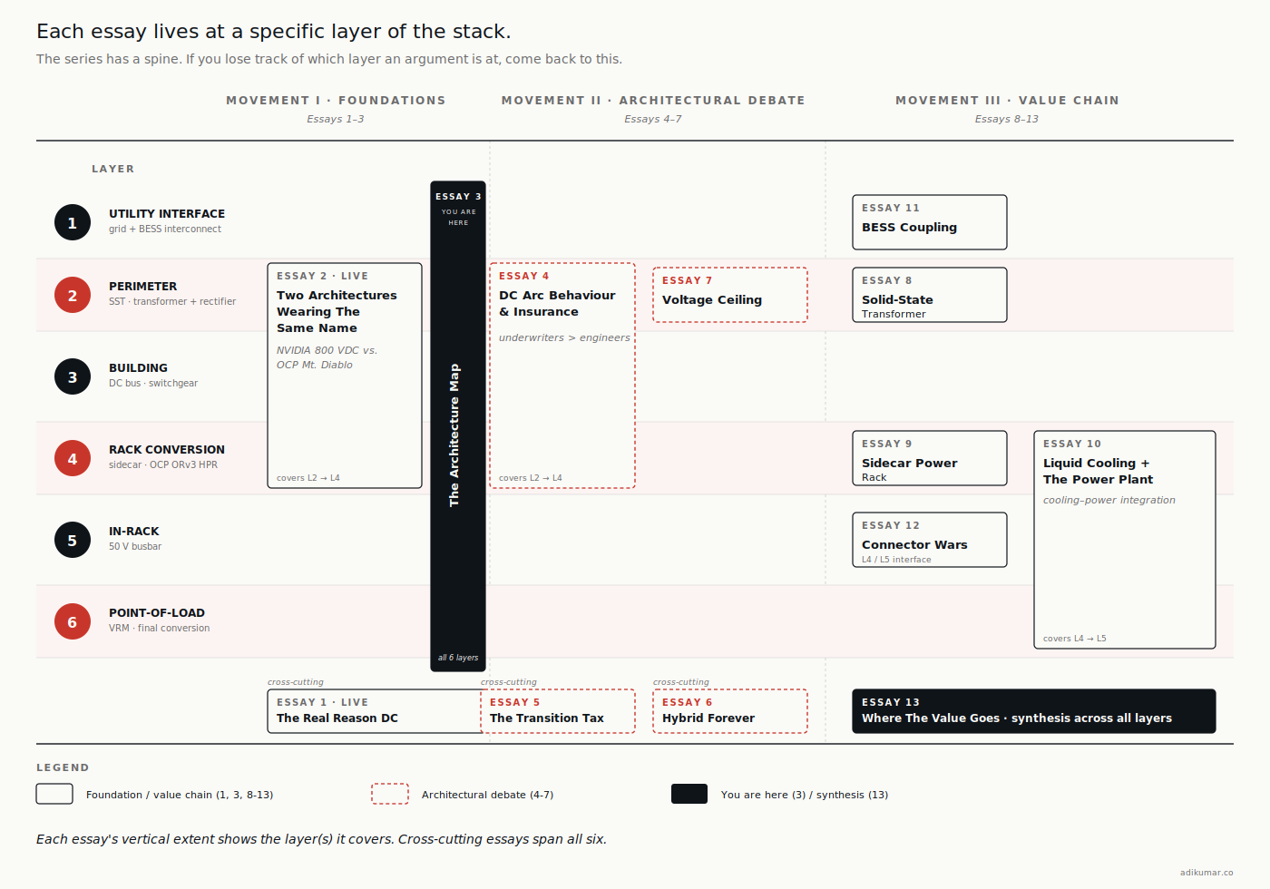
Each of the upcoming essays in The DC Transition lives at a specific layer of this map. Worth flagging now so you can place each one when it arrives.
- Essay 4 — DC Arc Behaviour and Safety. Cuts across Layers 2, 3, and 4. The protection regime is set by where the arc energy is highest, and that’s at the transitions between layers.
- Essay 5 — The Transition Tax. Cross-cutting again. The capex premium for DC architecture isn’t concentrated at any one layer; it accumulates across all six. Understanding which layers cost more matters for procurement allocation.
- Essay 6 — Hybrid Forever. The full case for §4 of this essay, expanded with operator economics and case-study deployment patterns.
- Essay 7 — The Voltage Ceiling. Layer 2 specifically, looking at the 1500 V / MVDC question.
- Essay 8 — The Solid-State Transformer. Layer 2, deep on supplier dynamics.
- Essay 9 — The Sidecar Power Rack. Layer 4, specifically the OCP-spec ecosystem.
- Essay 10 — Liquid Cooling and the Power Plant. A cross-cutting essay on the integration between cooling and power architecture, primarily affecting Layers 4 and 5.
- Essay 11 — BESS Coupling. Layer 1, with implications for Layer 2.
- Essay 12 — The Connector Wars. Layer 4 / Layer 5 interface specifically.
- Essay 13 — Where The Value Goes. Synthesis across all six layers with operator implications.
If at any point you lose the thread of which layer an essay is at, come back to this one. The map is the spine.
6. A note on disclosure and scope
This essay names Eaton in Layer 2 and Layer 3 of the vendor map. I work at Eaton. The disclosure block at the top of every essay in this series flags my employment relationship; this section adds the operational detail.
Where Eaton appears in this essay or any other in this series, it appears alongside its actual competitors and within its actual market position. I won’t overstate Eaton’s role in the transition; I won’t understate other suppliers’ roles to make Eaton look better; and I won’t write anything that could be construed as material non-public information about Eaton’s product roadmap. The discipline is straightforward: if I couldn’t say it on a public earnings call as a participant, I don’t say it here.
If you spot a place where I’ve gotten that wrong, tell me. The point of the disclosure isn’t to give me cover to write whatever I want — it’s to give readers the context to push back when they see bias.
7. The closing question for operators
If you’re inheriting an AI infrastructure budget in 2026, the most useful thing you can do this week is map your own architecture stack to these six layers. Specifically:
- For each layer, name the architecture you’ve committed to (or inherited from a previous decision)
- For each layer, name the vendor or vendors you’re locked into
- For each layer, name the standard you’re certifying against
- Identify which layer-to-layer interfaces are constraining your options at the next layer down
That exercise will tell you something most operators don’t know: where in the stack your degrees of freedom actually are. Most operators discover they have less freedom than they thought at Layers 4 and 5, and more freedom than they thought at Layers 2 and 3.
The architectural debate in trade press is about Layer 2 and Layer 3. The architectural lock-in is at Layers 4 and 5. The architecture-to-margin question is at Layer 2. Each of these gets its own essay. This one gives you the map.
Essay 4 looks at DC arc behaviour — the safety regime that’s quietly being written, and why insurance underwriters are about to have stronger opinions about your architecture choice than your engineers do.
Essay 3 of 13 in The DC Transition series. Subscribe to get each essay as it publishes.
Sources
- IEC 60038 Edition 7.0 (2009) and Amendment 1 (2021): voltage classification standard.
- IEC SC 8A: System aspects of low-voltage DC distribution working group, IEC TC 8.
- UL 98B (DC disconnect switches up to 1500 V): UL Standards database; ABB UL 98B 2 kV certification, July 2025; pv-magazine USA, July 17 2025.
- IEEE 1709 (Recommended Practice for Medium-Voltage DC Distribution): IEEE Standards Association.
- NEC Article 712 (DC microgrids, added 2017 NEC cycle): NFPA.
- OCP ORv3 specification: Open Compute Project, Open Rack v3 Base Specification.
- OCP ORv3 HPR specification: Open Compute Project, Open Rack v3 High Power Rack specification.
- OCP Diablo 400 specification v0.7.0, March 2026.
- OCP ORV3 HVDC-LVDC 100kW Power Shelf Design Specification v1.0.0: opencompute.org.
- Vendor positioning: company product disclosures and OCP marketplace listings (Eaton, Schneider, Hitachi Energy, ABB, Vertiv, Advanced Energy, Delta, Lite-On, Bel Power, Vicor, Infineon, TI, Analog Devices, Wiwynn, Foxconn, Quanta, Inventec, Supermicro).